ToyCollect V1.0 robot - Building instructions and software
2015/07/15
If you need stereo cameras, please consider building a V1.21 (R2X) or V1.3 (K3D) robot instead.
Here is all the information so you can build yourself an original ToyCollect V1.0 robot.
Hardware
First you need to go shopping. We will need...
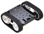 |
- 1x Zumo chassis kit (#1418)
- 2x 100:1 Micro Metal Gearmotor HP (#1101)
- 1x Basic Sumo Blade for Zumo Chassis (#1410)
- 1x Pololu Qik 2s9v1 Dual Serial Motor Controller (#1110)
- 1x 0.100" (2.54 mm) Breakaway Male Header: 1x40-Pin, Straight (#965)
- 1x Premium Jumper Wire 50-Piece Rainbow Assortment F-F 6" (#1700)
by Pololu Robotics and Electronics.
|
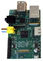 |
- 1x Raspberry Pi Model B (rev1) (#756-8308)
- 1x Raspberry Pi Camera Module (#775-7731)
- 1x Edimax low power WLAN adapter EW-7811UN (#760-3621)
- 1x Chassis for Model A/B (#764-4389)
by RS Components or any other convenient shop.
You will be able to use Raspberry Pi (RPi) Model A if you put the chassis back about 5mm or remove a small part of your Sumo blade for the WLAN USB card.
You will be able to use RPi Model B+ when you use another (or no) chassis.
Model B (rev1) had no mounting holes so we had to use a chassis, it adds about 7mm to height and is not essential. Note we used only the lower part of the chassis. |
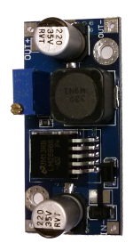 |
- 1x DC-DC Buck Step-Down Voltage Converter (based on LM2596)
You can get these cheap on eBay or Amazon. They can output up to 4A at 5V. You must set output voltage to 5V using a voltmeter and double-check! If you know what you are doing, you can use an IC with a fixed 5V output voltage (e.g. L78S05CV)
|
 |
- 1x at least 2GB SD card (or MicroSD card for Model B+) that is
compatible
with RPi. If you want to recompile TCserver, you need a full C++ toolchain
on the RPi - best use a larger SD card then (we use 32G)
- 1x Lumimicro LMFLC4500 or comparable very bright white LED which runs on 3.3V and does not need much more than 100mA - we are connecting directly to a GPIO port and it gives around 50mA which has this LED at half maximum brightness.
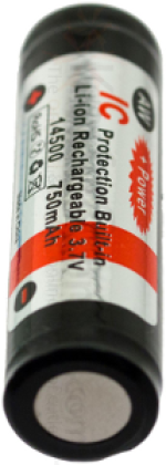
- at least 4x AA Lithium 1.5V batteries with at least 2900mAh charge each
OR 4x AA Lithium-Ion rechargable batteries with IC protection and at least 750mAh (these need a special charger)
Note that we have to get 5V plus the step-down transformers minimum voltage difference for the RPi and the motors, so we cannot use rechargable NiMH or NiCD batteries as these would only give 4.8V. We could of course have used a step-up/down voltage converter... The Lithium batteries are not rechargable but will run the robot for about 1.5 hours. The Lithium-Ion rechargable batteries will run the robot for about 2.5h. We therefore recommend the Lithium-Ion rechargable batteries. Available e.g. at Amazon, or just google "aw lithium rechargable 14500". The input voltage here is 3.7V * 4 = 14.8V - please check if your voltage convertor can process this!
|
Assembly
- Solder the breakaway male headers to the dual serial motor controller on the wrongback side (i.e. they should face down when looking at the front side). Connect the pins for fixed baud rate of 38400 permanently by soldering a small piece of the header over it - we don't have space for a proper jumper.
- Take away a part of the Sumo blade so the camera can see - removing a 5mm x 8mm (BxH, portrait) piece from the center part should suffice (left side of center part when looking from front). If you use a Model A, you also need to take something away around the middle of the center part, otherwise the USB connector would not be available. Use a metal saw or bolt cutter.
- Cut a few of the jumper cables apart and solder them to the two motors. The dual serial motor controller will be next to the 2x USB ports - the cables must be long enough to reach there. If you cut the cables next to one connector they will easily be long enough.
- We put the voltage converter upside-down on the bottom of the chassis which extends 2cm behind the Zumo platform. You must be able to connect the input of the voltage converter to the output from the battery compartment. The output of the voltage converter must reach the corresponding pins of the RPi. You must solder all connections directly to the voltage converter as there is too little space below. We soldered above and below (actually, male headers would have fit the IN+ and OUT+ connectors as these extend beyond the chassis). If you cut the cables next to one connector, they will easily be long enough.
Set output voltage to 5V using the small slotted screw on top of the light blue box while having an input voltage of at least 6V connected and measuring output voltage via voltmeter.
- Assemble the Zumo kit, including the motors and the blade.
- Attach the RPi using either the lower part of the chassis (B rev1), or the mounting holes if available. The Zumo platform has lots of small holes on top, you need very small nuts and screws.
- Do not connect the camera module yet, but plug the WLAN into the top USB.
- Cut another two jumper cables and solder their ends to the LED. These must reach GPIO18 on the RPi. Glue this on the camera (top-right position) and connect them.
- Connect everything else according to the wiring diagram.
- Check everything but especially the power connections.
Connecting 5V to a 3.3V connector, ground or GPIO will almost certainly kill your RPi.
Software
- Now is the time to download the RPi distribution of your choice, put it on the SD card and put it in. For now, connecting a micro USB cable for power is sufficient if you don't use the motors - you need a 4A 5V power supply for that. We use the Raspbian distribution and the following steps are for that distribution.
- Connect the camera. Don't route the cable yet.
- You need to configure overclocking (to 1GHz) via
sudo raspi-config, Overclock, at least High, preferably Turbo. For Turbo we advise using a stronger power supply for testing (at least 2A). We also put a small heatsink on the main processor to prevent overheating.
Also enable the camera in raspi-config. You will need to reboot.
- You need WLAN already available (i.e. existing WLAN infrastructure e.g. via any WLAN router). Configure WLAN and make sure the system automatically connects on bootup. Also configure SSH so you can remotely login to the machine for troubleshooting.
- Ensure your internet connection works and use the following commands to install necessary packages:
apt-get update
apt-get install netcat-openbsd libncurses5-dev
- Log into the Raspberry Pi and edit /etc/inittab as root. You need to comment out the last line which spawns a getty on the serial line ttyAMA0 since we have used this for connecting the serial motor controller. You might get away with sending a HUP signal to init and killing this getty, but to be safe... reboot.
- Use raspivid to show camera preview, then route the cable. Place
the camera module in front of the ethernet connector with the camera
connector facing right (i.e. 90° rotated) and route the cable under
the WLAN USB stick. If you see colored line interference, the cable
is bent too strongly. Alternate cable routing and checking, it's
sometimes tricky to make it work. You may need to unplug and replug
the WLAN usb adapter.
- Download the binaries from the link on the right. Alternatively,
download the sources and recompile yourself. Recompiling needs a C++
toolchain on the RPi itself, so you might need a larger SD card.
- Copy the control program TCserver to the RPi and start it manually via SSH. It should say "Connected" and output dots. If not, check previous steps and shown error messages (if any).
- While TCserver is running on the RPi, install TCclient-debug.apk
on an Android device of your choice (at least Android 4.1). It also needs to connect to the
same WLAN network. TCclient assumes the IP adress of RPi is
192.168.42.42, if it is not, you will need to click on the logo
(bottom center) and change this (TCclient will remember the new
setting when restarted). You should instantly
be able to control the robot. If not, click a few times on the
background outside the controls - this initiates a reconnect. On the
top there is a control for LED brightness. Try this one first as it
is safe. Moving means your robot will instantly move so this is the
time to switch to batteries.
- If everything works, copy TCserver to /usr/local/bin and add the following line to /etc/rc.local:
/usr/local/bin/TCserver &
This will ensure TCserver is started on each reboot.
Afterwards it should look somewhat like this.
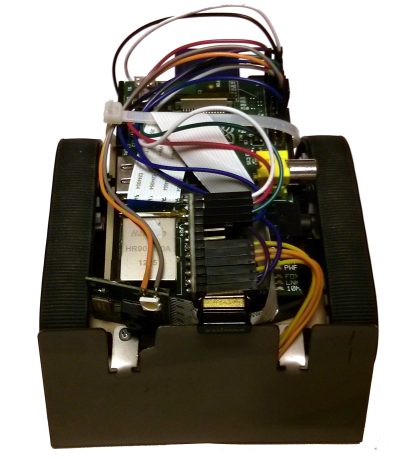
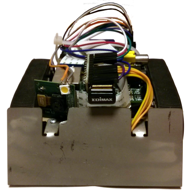
Enjoy! If something does not work as it should, contact us.