ToyCollect V1.1, V1.3 (K3D) robot - Building instructions
2018/07/15
If you want to build a V1.1 robot, remove Kùla Bebe and its mount and add a Sumo Blade.
Here is all the information so you can build yourself a ToyCollect V1.1 or V1.3 (K3D) robot.
Hardware
First you need to go shopping. We will need:
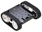 |
- 1x Zumo chassis kit (#1418)
- 2x 100:1 Micro Metal Gearmotor HP (#1101)
- Only for V1.1: 1x Basic Sumo Blade for Zumo Chassis (#1410)
- 1x Pololu Qik 2s9v1 Dual Serial Motor Controller (#1110)
- 1x 0.100" (2.54 mm) Breakaway Male Header: 1x40-Pin, Right Angle
(#967)
- 1x Premium Jumper Wire 50-Piece Rainbow Assortment F-F 6"
(#1700)
by Pololu Robotics and Electronics. Many parts are also available at EXP-Tech, BuyZero or Conrad.
|
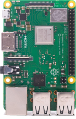 |
- 1x Raspberry Pi Model 3B+ with16G MicroSD card (#172-0556)
- 1x Raspberry Pi Camera Modul V2 (#913-2664)
- 1x Chassis for 3B+ (#167-7048, use without lid)
by RS Components or many other shops
(e.g. EXP-Tech, BuyZero, Conrad - see above). Part number is always by RS Components.
Any chassis can be used, provided it has holes on top for the 2x20 pins, a flat camera cable can be routed through to the outside, and holes can be drilled to fix components and the robot base to the chassis with screws and nuts. Even a RPi 4 can be used, but would need a different chassis. Wifi is integrated so the Wifi USB card from V1.0 is no longer necessary. |
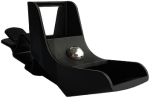 |
- Only for V1.3:1x Kùla Bebe double periscope (available here)
With this double periscope - actually just four very precisely mounted mirrors - we can make a stereo camera out of a normal camera. However, the field-of-view is significantly reduced.
|
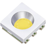 |
- 1x LED White PLCC6 (#156428-7M, available by Conrad)
Since the original LED is no longer available, just take a compatible one with IF ~ 100mA or smaller, UF ~ 3.3V, brightness ~ 45,000 mcd and radiation angle ~ 50°.
|
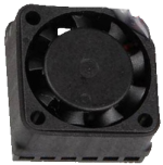 |
- 1x Heatsink with active fan (#1553480-7M)
From RPi 3B+ onward an active cooling system is advised as the robot overheats quite fast. A passive heatsink is no longer sufficient.
|
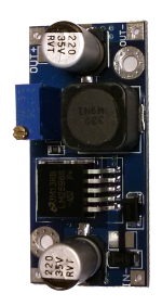 |
- 1x DC-DC Buck Step-Down Voltage Converter (based on LM2596)
You can get these cheap on eBay or Amazon. They can output up to 4A at 5V. You must set output voltage to 5V using a voltmeter and double-check! If you know what you are doing, you can use an IC with a fixed 5V output voltage (e.g. L78S05CV)
|
 |
- Only if you do not have a MicroSD card yet: 1x at least 8GB MicroSD card that is
compatible
with RPi. If you want to recompile TCserver - which is essential for the new control software - you need a full C++ toolchain
on the RPi and should best use a larger MicroSD card (we use 32G)
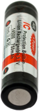
- at least 4x AA Lithium 1.5V batteries with at least 2900mAh charge each
OR 4x AA Lithium-Ion rechargable batteries with IC protection and at least 750mAh (these need a special charger)
Note that we have to get 5V plus the step-down transformers minimum voltage difference for the RPi and the motors, so we cannot use rechargable NiMH or NiCD batteries as these would only give 4.8V. The Lithium batteries are not rechargable but will run the robot for about 1.5 hours. The Lithium-Ion rechargable batteries will run the robot for about 2.5h. We therefore recommend the Lithium-Ion rechargable batteries. Available e.g. at Amazon, or just google "aw lithium rechargable 14500". The input voltage here is 3.7V * 4 = 14.8V - please check if your voltage convertor can process this!
|
Assembly
- Solder the breakaway angled male headers to the dual serial motor controller. The side is irrelevant, we have the back side (without parts) on top. Connect the pins for fixed baud rate of 38,400 permanently by soldering a small piece of the header over it - we don't have space for a proper jumper. Mount it using M2 screws and safety nuts using the two PCB mount holes (if necessary, drill corresponding holes into the chassis)
- Only for V1.1: Take away a part of the Sumo blade so the camera can see - removing a 5mm x 8mm (BxH, portrait) piece from the center middle part should suffice. Use a metal saw or bolt cutter.
- Cut a few of the jumper cables apart and solder them to the two motors. The dual serial motor controller will be next to the 2x USB ports - the cables must be long enough to reach there. If you cut the cables next to one connector they will easily be long enough.
- Assemble the Zumo Kit including motors - for V1.1 also the Sumo-Blade - according to instructions by Pololu.
- Attach the RPi via the lower part of the chassis, making use of existing mounting holes. The Zumo platform has lots of small holes on top, you need very small nuts and screws. M2.5 should fit. Due to space restrictions no safety nuts will fit, we therefore suggest a drop of bolt adhesive to prevent the gradual loosening during driving. Normally this should not be a problem unless you often drive over uneven ground.
- Since mounting the camera usually precludes access to the SD-card, this is the time to install the RPi 3B+.
- Download the RPi software distribution of your choice - we use the Raspbian Lite Distribution. Copy the image to the microSD-Card and insert it. Attach an USB keyboard and a HDMI monitor, then connect power via micro-USB.
- You need Wifi already available (i.e. existing Wifi infrastructure such as any Wifi router). Configure Wifi - a static IP address is preferrable if supported by the router - and make sure the system automatically connects on bootup. Also configure SSH so you can remotely login to the machine for further installation and troubleshooting.
- Deactivate the graphics user interface. Autologin should be off.
- Test if after reboot Wifi is automatically connected and you can access the RPi 3B+ via SSH.
- Connect the camera with a fitting flat ribbon cable, move it into the chassis and mount the camera with M2 screws and nuts to the front side of the chassis (if necessary, drill holes again). It is sufficient to use either the top two or the bottom two mount holes, however you may need hot glue or a double-sided adhesive band to fix the camera in position. Check that the camera is mounted straight horizontally and preferably use plastic nut as spacers.
- Cut the mounting part with the hole from the Kùla Bebe mount - where the double periscope is mounted (using a saw, bolt cutter or by careful multiple folding over a rules) and use hot glue to put it on the camera PCB such that the camera looks out from the middle. NOTE: No hot glue must drop on the camera! It should then look like the sample on the right. If this is too sloppy for you: a 3D printed mount should be feasible - if you create one and test it, we'll be happy to link you!
- Cut another two jumper cables and solder their ends to the LED. These must reach GPIO18 on the RPi. Glue this on the camera or on Kùla Bebe (top-center position) and connect them as shown in the wiring diagram.
- We put the voltage converter upside-down on the bottom of the chassis which extends 2cm behind the Zumo platform. You must be able to connect the input of the voltage converter to the output from the battery compartment. The output of the voltage converter must reach the corresponding pins of the RPi. You must solder all connections directly to the voltage converter as there is too little space below. We soldered above and below (actually, male headers would have fit the IN+ and OUT+ connectors as these extend beyond the chassis). If you cut the cables next to one connector, they will easily be long enough.
Set output voltage to 5V using the small slotted screw on top of the light blue box while having an input voltage of at least 6V connected and measuring output voltage via voltmeter.
- Connect everything else as in the wiring diagram. Don't forget the fan! Since there are insufficient 5V and Ground connections, at least two Y-cable are needed. The simplest way is to split the jumper cables and solder several of them together, afterwards isolating them with electrician's tape or heat shrink tubing. For the missing Ground connection you can also solder an additional connect on the back side of the motor controller ground pin. As an alternative use a crimping tool (according to our experience, up to three AWG27 cables can be crimped together although it is quite tricky) which can also be used to make your own jumper cables, or use very small ferrules.
- Check everything but especially the power connections.
Connecting 5V to a 3.3V connector, ground or GPIO will almost certainly kill your RPi.
Afterwards it should look somewhat like this.


Software
Generally the same control software as for the V1.0 robot can be used. However, if you want to use pretrained deep-learning models with Tensorflow Lite, you need to install new control software and at least a Raspberry Pi 3B+.
Enjoy! If something does not work as it should, contact us.