ToyCollect V1.21 (R2X) robot - Building instructions
2019/07/30
Here is all the information so you can build yourself a ToyCollect V1.121 (R2X) robot.
Hardware
First you need to go shopping. We will need:
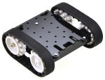 |
- 1x Zumo Chassis Kit (#1418)
- 2x 100:1 Micro Metal Gearmotor HP (#1101)
- 1x Pololu Qik 2s9v1 Dual Serial Motor Controller (#1110)
- 3x 5V Step-Up/Step-Down Voltage Converter S9V11F5 (#2836)
- 1x Mini MOSFET Slide Switch with Reverse Voltage Protection, LV (#2810)
- 1x 0.100" (2.54 mm) Breakaway Male Header: 2x40-Pin, Right Angle
(#2668)
- 5x 0.100" (2.54mm) Extended Male Header (#1114)
by Pololu Robotics and Electronics. Many parts are also available at EXP-Tech, BuyZero or Conrad.
|
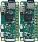 |
- 2x Raspberry Pi Zero W w/o Pins (b-pzw-board)
- 2x Raspberry Pi Camera Module V2 (a-cam2)
- 2x Raspberry Pi Camera Pi Zero Cable Short (a-zero-camcable-short)
by BuyZero or many other shops (e.g. EXP-Tech, BuyZero, Conrad - see above). Part number is always the one by BuyZero.
NOTE: For each order only one RPi Zero W without pins can be delivered. So we suggest ordering a Pi Zero W Essentials Kit (k-pzw-essentials) with loose pin header instead. A HDMI and an USB adapter are in any case essential for the installation.
|

|
- 2x LED White YZ-WS5N40N wired (#185811-7M, available by Conrad)
Any other LED with 5mm diameter can be used, provided UF ~ 3.3V and IF ~ 50mA since the RPi Zero W does not output more power than this.
- 1x TOOLCRAFT 88200 plastic-grooving screw 2.5mm 8mm 100 pieces (#485048-7M, available by Conrad, we just need 8 pieces - you can also use self-tapping screws, e.g. #888700-7M)
- 10x TOOLCRAFT DIN7981 C-H 2.2x4.5 filister head self tapping screw 1 piece (#889177-7M, available by Conrad)
Other computer screws, self-tapping or wood screws may also be usable. Just try them!
|
 |
- 2x at least 8GB MicroSD-card, which is
compatible
with the RPi. If you want to record deep learning training data, we recommend 128G cards (at least Class 10 U3) which are sufficient for 10h recording time. We have had good results with the Samsung EVO Plus series.
- at least 4x AA Alkaline 1.5V batteries
OR 4x AA NiMH 1.2V batteries
OR 4x AA NiCD 1.2V batteries
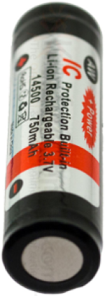
OR 4x AA Lithium-Ion 3.7V rechargable batteries with IC protection and at least 750mAh (these need a special charger)
This robot can use rechargable batteries as well normal alkaline batteries thanks to the step up/down converter. Since Alkaline batteries only offer a one-time runtime of 2.5h, we recommend NiMH or Lithium-Ion rechargable batteries for heavy users.
|
Assembly
- This robot has a 3D printed chassis which consists of three modular parts. The design has been done by Lucdesign. You can print either three single parts separately (printing time about 2.5h for each part, 7.5h total) and glue them together with super adhesive, or print the combined model where all parts have been combined into a single model (total printing time about 8.5h). If you don't have a 3D printer, you can also let the design be printed at Thingiverse or elsewhere.
- For this robot we need dupont (jumper) cable with precise lengths. You will therefore need a crimping tool, dupont plugs and pins as well as colored rainbow cable (AWG27 is sufficient). The colors correspond to those of the wiring diagram below. Unless otherwise noted, both ends of the cable are to be crimped with dupont plugs. Do not add the housing yet since several cables are combined into one housing! We recommend checking every cable after crimping with two test pins and a voltage meter, since badly crimped cable is one of the most common problems during assembly.
| Cable | Length excl. housing
(in cm) |
|---|
| LED (2x red, 2x black; one end per cable soldered to a LED) | 8 |
| Gray, White (connection between both RPis) | 15 |
| Pink, Blue (connection to motor controller) | 13 |
| Black, Dark Red (Logic power supply for Motor Controller) | 13 |
| 2x Yellow, 2x Green (Motor, one end open per cable) | 7 |
| Voltage Converter <=> RPi 1 (1x red) | 7 |
| Voltage Converter <=> RPi 2 (1x red) | 16 |
| Voltage Converter <=> Motor Controller VMOT (1x red) | 9 |
Voltage Converter <=> RPi1,2/VMOT
Y-Cable with 4 ends (all black) | <1 (soldered directly to VC)
7 (RPi1)
9 (VMOT)
16 (RPi2) |
- First, split the 40x2 angled pins into 2x 20x2 Pins and solder these to the back side of each Raspberry Pi Zero Ws such that the pin connectors (i.e. where you would attach dupont plugs) are available on the unpopulated side of the PCB board. On the right you see how it should look like. To ensure correct distance please connect dupont cables with housing at both ends before soldering.
- Solder the straight pins to the motor controller. This time, pin connectors should go to the populated side of the PCB.
- Connect each camera by the short camera cable to one RPi Zero W. Consider the orientation of the cable: the black markings should be the same as in the wiring diagram below.
- Solder the three voltage converters together as shown in the diagram on the right. A 2x1 dupont plug connects the input power supply from top. If the remaining pin length after soldering is too short, just solder a short cable with dupont pins on it. The voltage outputs (VOUT) are connected to both RPi Zero Ws as well as the motor power supply (VMOT). Here, we take the previously unused angled pins from the motor controller. For the corresponding Ground connections we need a Y-cable with four endings, which is soldered at the bottom center pin. For the VIN/GND connections to the power supply, we use the extended male headers and remove the spacers from one side. These can later be used as spacers between the first two voltage converters.
If this is too difficult, you can solder only two voltage converters together - for RPI 1 and 2 - and connect VMOT directly to the battery. However, this means the robot will become slower if the batteries run down and you must not use Lithium-Ion chargable batteries as the motors would be destroyed.
- Solder the open ends of the green/yellow cables directly to the two motors as shown in the wiring diagram. Each motor must receive a green and a yellow cable. The other ends of each cable are collected in a 4x1 dupont housing (alternating yellow and green where the cables from the same motor are always adjacent).
- Assemble the Zumo Kit including motors according to instructions by Pololu.
- Using hot-melt adhesive, fix the slide switch to the upper side of the robot base, and solder the battery contacts to the input side of the switch. Its position should be roughly between motors and front and on the right-hand side with the slide switch facing outwards. This ensures the switch is reachable even with attached 3D chassis. On the output side, solder the open ends of a 2x1 dupont cable with housing, which will later be connected to the battery input side of the voltage converter.
- The LEDs are soldered to the open ends of each cable (Red is plus or anode, black is minus or cathode) and fixed with super adhesive into the corresponding holes of the 3D chassis. For testing purposes it is sufficient to plug them in and possibly fix them later with hot-melt adhesive.
- Connect everything else as in the wiring diagram. The gray rectangles show which dupont plugs are put into a common housing. Consider pin orientation! The dupont plugs are connected on the back side of the RPis and therefore must be assembled in a mirrored form. Best start with a 2x2 housing and check each connection.
- Check everything but especially the power connections.
Connecting 5V to a 3.3V connector, ground or GPIO will almost certainly kill your RPi.
- Since the next steps will partially prevent access to the HDMI and USB connector, this is the time to install both RPi Zero Ws.
- Download the RPi software distribution of your choice - we use the Raspbian Lite Distribution. Copy the image to both microSD-Cards and insert them. Attach an USB keyboard and a HDMI monitor (via MiniHDMI and micro-USB adapters), then connect power via micro-USB.
- You need Wifi already available (i.e. existing Wifi infrastructure such as any Wifi router). Configure Wifi - a static IP address is preferrable if supported by the router - and make sure both systems automatically connect on bootup. Also configure SSH so you can remotely login to both systems for further installation and troubleshooting.
- Deactivate the graphics user interface. Autologin should be off.
- Test if after reboot Wifi is automatically connected and you can access both RPi Zero Ws via SSH.
- Fix each RPi Zero W (remove the microSD card first as it breaks easily!) with four plastic grooving screws to the middle part of the chassis. Motor Controller and both cameras are fixed to the front part of the chassis using the smaller self-tapping screws. It should then look similar as on the right.
- The soldered threefold voltage converter is fixed along its longest axis to the middle stay on the left side using hot-melt adhesive (battery connector to the back, away from the cameras) and afterwards the power connectors are attached or directly soldered. If you solder the connectors for Ground and power directly on, please make sure the cable lengths are sufficient for later disassembly without desoldering.
- Now put the robot base into the chassis. Check that there are no cables in the way, and connect the power cable from the slide switch to the voltage converter. The motor cable must be routed to the front where the motor controller was mounted. The elevated platform in front (upper middle, marked red) is fit into the corresponding deepness in the robot base. The back supports are for the opposite corners (lower left and right, marked red). Connect the motor cable to the motor controller and fix the robot base to the chassis using a long screw and safety nut.
- Finally, reinsert the microSD cards (best with pincers), put in batteries, and slide the on/off switch to on. Both RPi Zero Ws should boot, connect with Wifi and be accessible via SSH within 1-2 min. Done!
Afterwards it should look somewhat like this.


Software
For this version of ToyCollect robot, the new control software must be used.
Enjoy! If something does not work as it should, contact us.